


Cylindrical
LiFePO4 cylindrical cells are all made of the same basic components. Each cell, and the entire battery, is enclosed by a resilient plastic container. Inside the container there is a “rolled” foil, and between the foil there is a layer of permeable “separator” material. A safe, nonflammable electrolyte (unique to LiFePO4) is added to each cell and saturates the “foil” and “separator”. The battery terminals are typically threaded (rather than posts) so that heavier-duty connections can be made to the load.
History of Lithium-ion Batteries
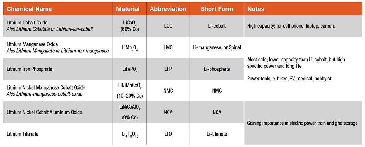
Experimental lithium batteries were developed as early as 1912, but it took nearly 70 years before a commercial lithium battery was developed for a wide market. Today, lithium batteries are most associated with enhancing “portable” capabilities. For example, they are the standard battery technology for high performance in portable electronics ranging from cell phones to laptop computers. There is a diverse family of lithium chemistries available. At first glance, they might all seem to be the same, but there are exploitable, distinct differences between them. The unique nature of the various chemistries allows each type to fill special application niches.
Even with wide market adoption in the early 1990s, as societal demands for lightweight portable electronics was burgeoning, the high cost barrier and complexities in battery management circuits would prevent lithium batteries from being used widely in support of larger devices or in scaled energy-storage systems such as large vehicles or uninterruptible power supply (UPS) systems.
Today, lithium battery technology continues to evolve at a rapid pace. Manufacturers, driven by demands from new applications, are constantly pushing the envelope by making changes in the chemistry and structure in search of improved battery life and greater energy density.


History of Lead-acid Batteries
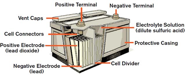
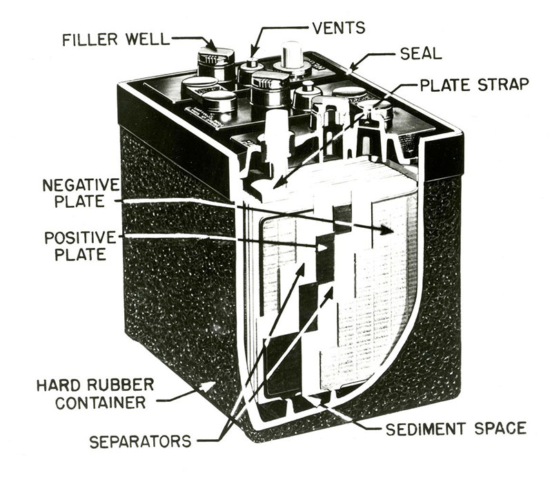
Lead-acid is the oldest rechargeable battery technology in existence. Invented by the French physicist Gaston Planté in 1859, lead-acid was the first rechargeable battery to be used in commercial applications. More than one hundred fifty years later, we still have no real cost-effective alternatives for cars, boats, RVs, wheelchairs, scooters, golf carts, and UPS systems.
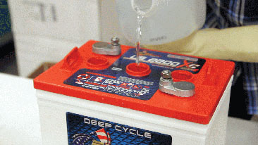
The lead-acid battery is still the most widely used 12 V energy storage device. A lead-acid battery is an electrical storage device that uses a chemical reaction to store and release energy. It uses a combination of lead plates and an electrolyte to convert electrical energy into potential chemical energy and back again.
There are many newer battery technologies available in the marketplace. However, lead-acid technologies are better understood and are widely accepted as the standard by which all other batteries are measured. Newer technologies often have operational constraints, including maximum and minimum operating temperatures and special charging requirements that make them less versatile and useful for the average consumer in everyday applications.
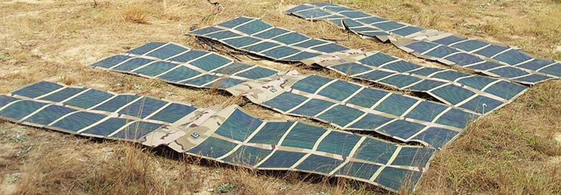
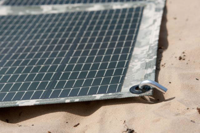
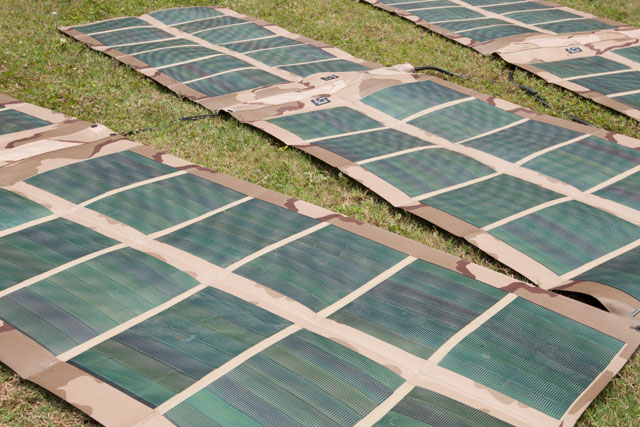
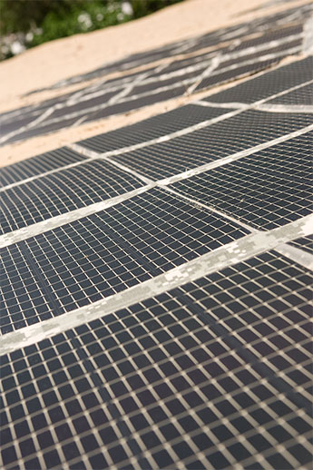
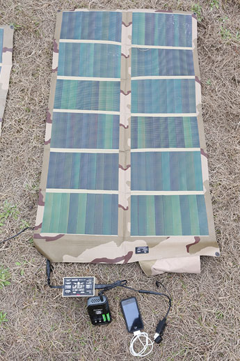
Amorphous Silicon Solar PV Panel
Amorphous silicon is the oldest thin-film technology and arguably the best. When laid on a substrate, amorphous silicon does not require a grid configuration to conduct electricity, allowing it to be used on large areas with ease. However, it does not conduct as well as crystalline silicon solar PV cells used in rigid panel technology because the connections between the silicon atoms are not as consistent. This inconsistency results in interrupted electron flow.
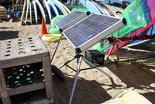
Numerous substrate materials can be used with amorphous silicon, making the technology highly adaptable. Polymer plastic is one option for substrate. Because polymer plastic is flexible and able to be folded or rolled, it excels in applications requiring ease of storage or transport.
Amorphous silicon solar PV panels perform better in low light intensities. This makes amorphous silicon a good choice for environments with interrupted sunlight or dusty conditions.
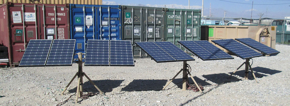

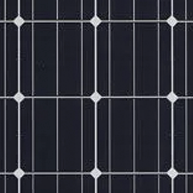
A rigid monocrystalline solar PV panel is distinctly recognizable by the arrangement of the individual solar PV cells (squares with no corners) that appears as a uniform, flat color.
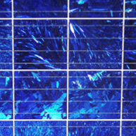
The surface of a rigid multi- or polycrystalline solar PV panel has the appearance of a rectangular grid and more of a bluish speckled color.
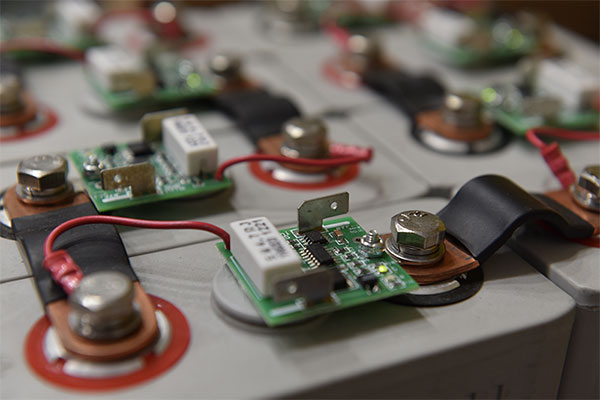

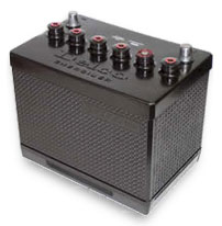
Most industrial flooded deep-cycle batteries use lead-antimony plates. Antimony is a metal that stiffens the lead plate and helps prevent battery failure due to structural failure of a plate. This improves the plate’s life but increases gassing and water loss. Antimony is not necessary in AGM batteries due to the rigid construction of the overall battery.


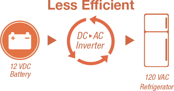

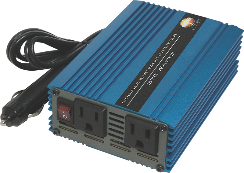
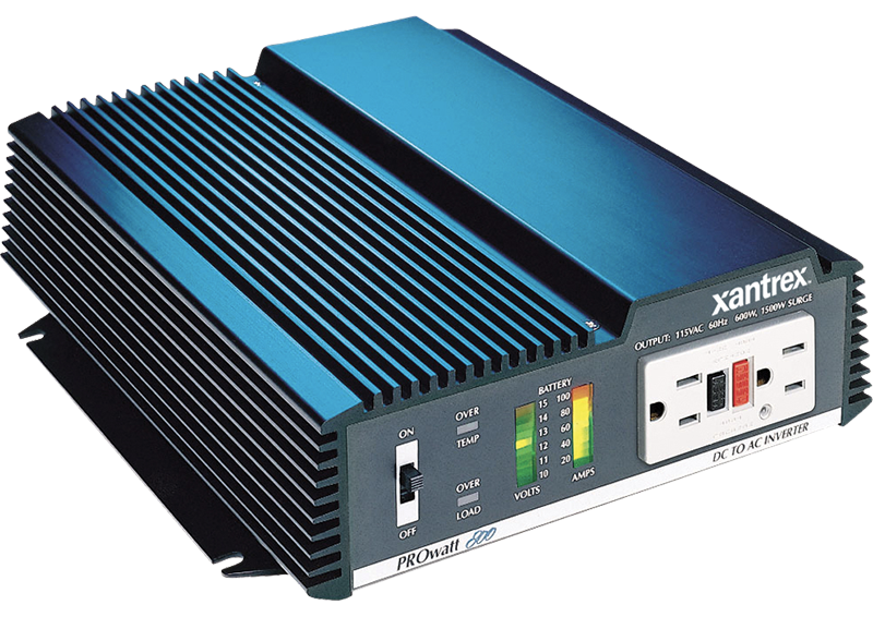
The following appliances may experience problems when operated from MSW inverters:


History of Lead-acid Batteries
Lead-acid is the oldest rechargeable battery technology in existence. Invented by the French physicist Gaston Planté in 1859, lead-acid was the first rechargeable battery to be used in commercial applications. More than one hundred fifty years later, we still have no real cost-effective alternatives for cars, boats, RVs, wheelchairs, scooters, golf carts, and UPS systems.
The lead-acid battery is still the most widely used 12 V energy storage device. A lead-acid battery is an electrical storage device that uses a chemical reaction to store and release energy. It uses a combination of lead plates and an electrolyte to convert electrical energy into potential chemical energy and back again.
There are many newer battery technologies available in the marketplace. However, lead-acid technologies are better understood and are widely accepted as the standard by which all other batteries are measured. Newer technologies often have operational constraints, including maximum and minimum operating temperatures and special charging requirements that make them less versatile and useful for the average consumer in everyday applications.