

Sometimes terms like “solar panel”, “photovoltaic cell”, or “PV panel” are used interchangeably when solar power is being discussed or described. They shouldn’t be.
When talking about solar power generation, there are two mainstream technologies:
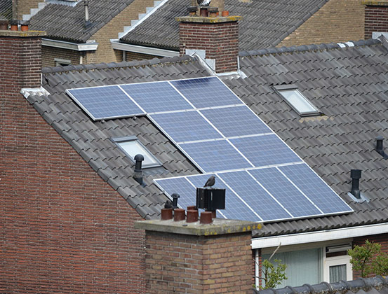
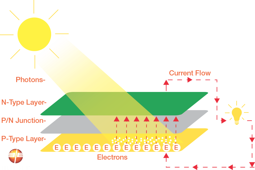
Typically when people talk about solar cells, panels, or arrays they’re visualizing the panels they’ve seen on rooftops or out in fields. This is photovoltaic solar power generation, which is the solar technology that’s explained in STIKopedia and used in all Solar Stik Systems.
There are many different types of solar PV panels on the market, and for every panel type there are even more manufacturers. The chemistry, construction, and performance vary greatly between panels.
For years, companies have sought ways to reduce manufacturing costs associated with traditional PV technologies. This search has resulted in several types of technologies over the course of the industry’s evolution.
The two most common types of solar panel technologies are rigid (mono- or polycrystalline)  and flexible (thin film) .
How to Read the Electrical Ratings Tag on a Solar PV Panel
Each module is rated by its DC output power under standard test conditions (STC) by the manufacturer.

Peak Power (Pmax) – the sweet spot of the solar panel power output, where the combination of the volts and amps results in the highest wattage; it is the point at which the MPPT electronics try to keep the volts and amps to maximize the power output
Voltage (Vmpp) – the voltage when the power output is the greatest; it is the actual voltage you want to see when it is connected to the MPPT solar equipment under STC
Current (Impp) – the current (amps) when the power output is the greatest; it is the actual amperage you want to see when it is connected to the MPPT solar equipment under STC
Open Circuit Voltage (Voc) – the volts the solar panel outputs with no load on it; it is the maximum voltage that the solar panel can produce under STC
Short Circuit Current (Isc) – the amps (current) the solar panels are producing when not connected to a load but when the plus and minus of the panel’s wires are directly connected to each other; it is the highest current the solar panels will produce under STC

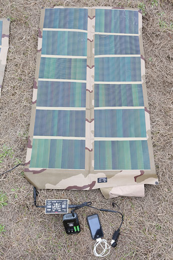
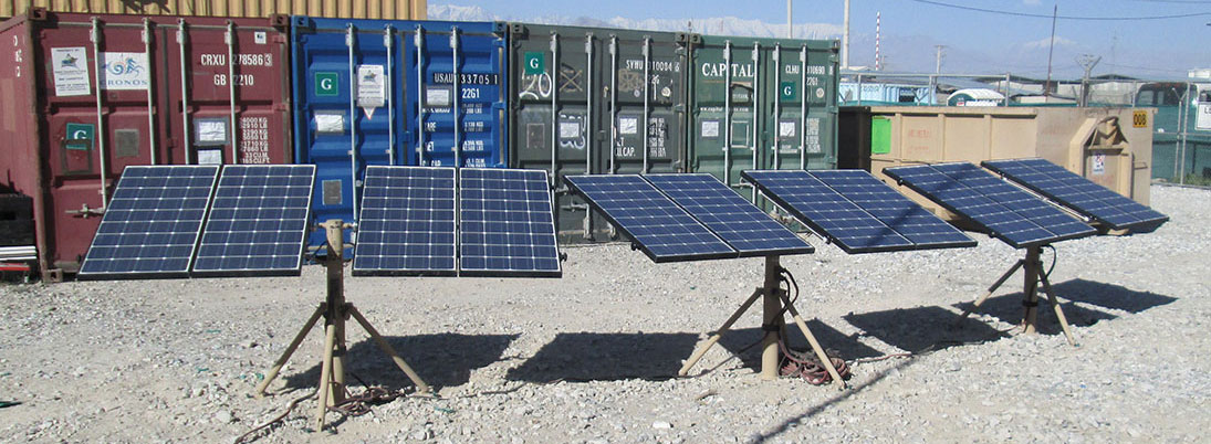
Not all solar panel types are suitable for every application. Rigid panels aren’t ideal for expeditionary applications. Flexible panels sustain damage when deployed in wet environments and water is allowed to pool on the cells.


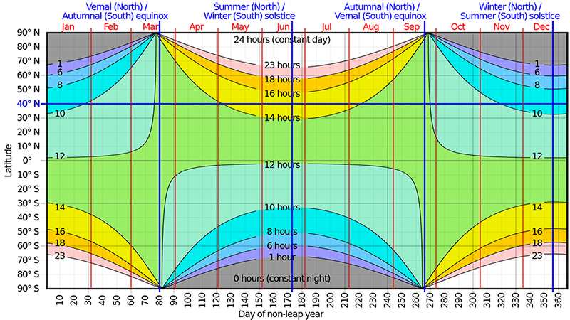
This chart illustrates the sunlight one can expect during any time of the year at any latitude and in either hemisphere. The horizontal blue line highlights the seasonal variation of the hours of sunlight at 40º N latitude. This parallel crosses through or near to Chicago, Istanbul, Beijing, and Madrid.

Solar PV Panel Construction
Photovoltaic cells (the part of the panel that produces electricity) are encapsulated using multiple layers of materials, which have the potential to alter the heat flow into and out of the PV module. The internal operating temperature of the the PV module is influenced by the amount and type of materials used in the construction and, in some cases, has a major impact on the PV module by reducing its voltage, thereby lowering the output power.
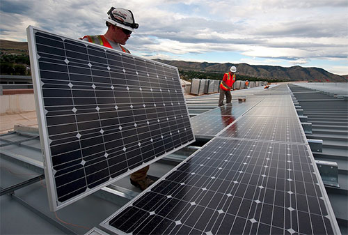
Mounting of the Solar PV Panel
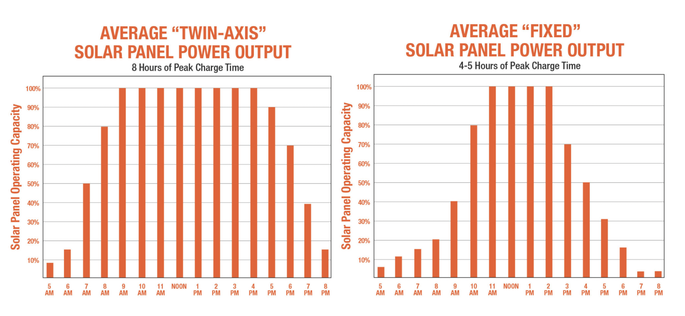
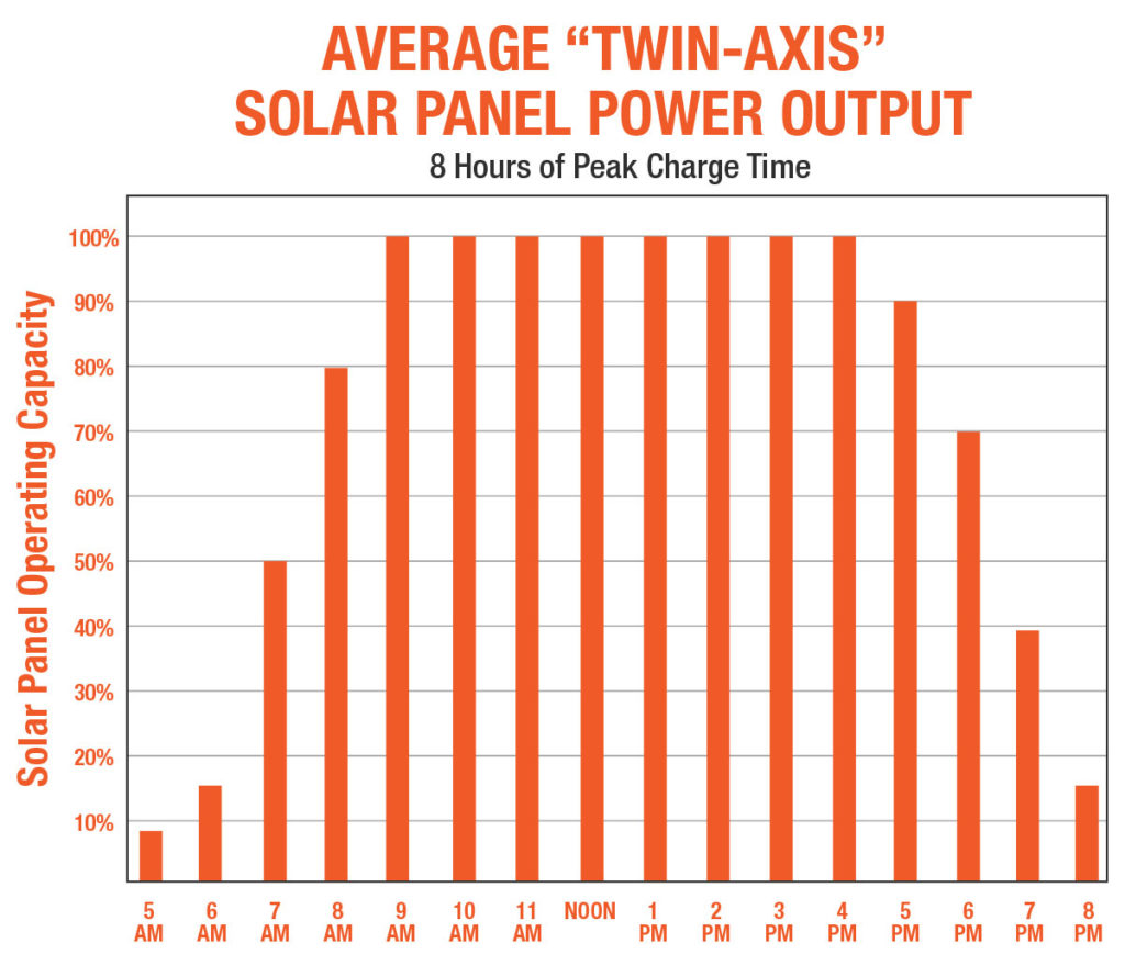
Panel arrays that track the sun automatically or manually, using multiple axes of movement, allow panels to work at 100% of rated output in direct sunlight for a longer period during the day. These arrays generate higher power output for longer times than fixed-angle or single-pitch systems and can adapt to seasonal changes of the sun’s path (declination) across the sky and the daily East-West travel of the sun.
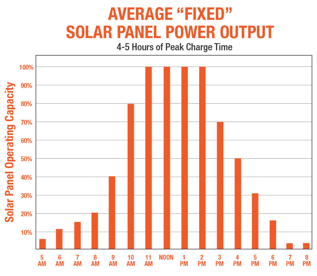
The sun rarely passes directly overhead during the course of a year. Most solar panels mounted in fixed-angle or flat positions (facing straight up) operate at reduced capacity, even during the noon hour. Single-axis solar PV panels often are adjusted only for seasonal changes in the angle of the sun (horizontal axis), but have limited ability to track the daily East-West progression of the sun’s travels. Single-axis tracking is extremely important for arrays that are located in far northern or southern latitudes.
A solar PV array that has a multi-axis tracking system often is as effective as a fixed-mounted panel system two to three times its size. Tracking requires as few as three daily panel adjustments to produce 100% of their rated power output all day long. With tracking, users can achieve 200% to 300% increases in power output over stationary or single-axis systems, depending on geographic location and time of year.
The method of mounting a solar PV panel plays a significant role in the panel’s ability to dissipate heat through one of three mechanisms: conduction, convection, and radiation. These heat-loss mechanisms depend on the thermal resistance of the module materials, the emission properties of the PV module, and the ambient conditions (particularly wind speed) in which the module is mounted. Mounting the panel away from other hot surfaces (such as a roof) will also aid significantly in cooling the panel.
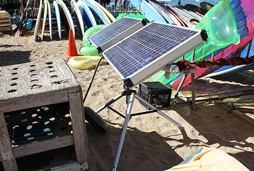
The Solar Stik design features a mechanical arm that allows panel adjustment to maximize solar exposure. A Solar Stik also suspends the panels, allowing good air circulation that keeps the panels cooler and operating at maximum power output.
The following graphs demonstrate the differences in power production between a flat or fixed solar PV array and one that is adjustable on two axes of rotation.
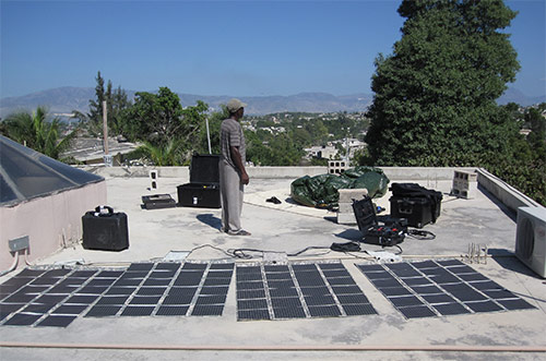
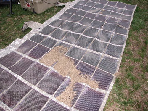
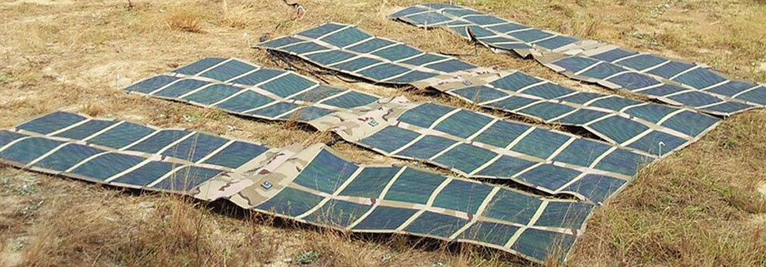
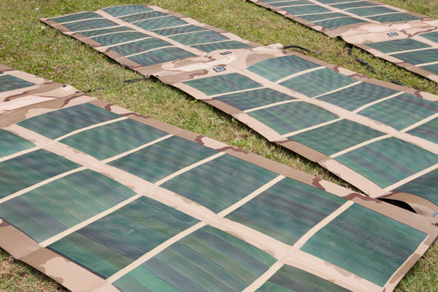
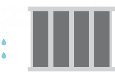
Often, thin-film solar PV arrays are deployed on the ground because of their physical size or application requirements. Such placement can result in negative effects for solar PV panels, including
Operators using thin-film solar PV panels laying on the ground should expect a 40% loss of the array’s rated power output. The easiest way to combat these issues is to deploy extra panels or to raise them slightly off the ground to allow for better airflow and angle to the sun.
Photovoltaic cells (the part of the panel that produces electricity) are encapsulated using multiple layers of materials, which have the potential to alter the heat flow into and out of the PV module. The internal operating temperature of the the PV module is influenced by the amount and type of materials used in the construction and, in some cases, has a major impact on the PV module by reducing its voltage, thereby lowering the output power.
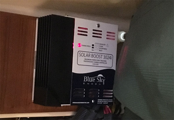
The name “Maximum Power Point Tracking” can be confusing to users at first encounter because the word “tracking” implies the device tracks the sun. This is not the case; an MPPT solar charge controller is an electronic device.


When using thin-film PV panels, it may be possible to daisy-chain connectors to add thin-film PV panels to an array, allowing operators to scale their systems to meet their power requirements. Connecting additional panels does not always provide an increase in power because the small wiring in the construction of many thin-film PV panels limits the amount of power they can safely conduct. Consult the panel’s literature for information about adding panels.


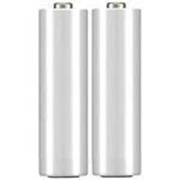
Cylindrical
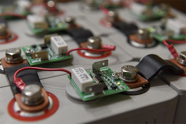
LiFePO4 cylindrical cells are all made of the same basic components. Each cell, and the entire battery, is enclosed by a resilient plastic container. Inside the container there is a “rolled” foil, and between the foil there is a layer of permeable “separator” material. A safe, nonflammable electrolyte (unique to LiFePO4) is added to each cell and saturates the “foil” and “separator”. The battery terminals are typically threaded (rather than posts) so that heavier-duty connections can be made to the load.
History of Lithium-ion Batteries
Experimental lithium batteries were developed as early as 1912, but it took nearly 70 years before a commercial lithium battery was developed for a wide market. Today, lithium batteries are most associated with enhancing “portable” capabilities. For example, they are the standard battery technology for high performance in portable electronics ranging from cell phones to laptop computers. There is a diverse family of lithium chemistries available. At first glance, they might all seem to be the same, but there are exploitable, distinct differences between them. The unique nature of the various chemistries allows each type to fill special application niches.
Even with wide market adoption in the early 1990s, as societal demands for lightweight portable electronics was burgeoning, the high cost barrier and complexities in battery management circuits would prevent lithium batteries from being used widely in support of larger devices or in scaled energy-storage systems such as large vehicles or uninterruptible power supply (UPS) systems.
Today, lithium battery technology continues to evolve at a rapid pace. Manufacturers, driven by demands from new applications, are constantly pushing the envelope by making changes in the chemistry and structure in search of improved battery life and greater energy density.


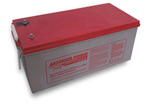
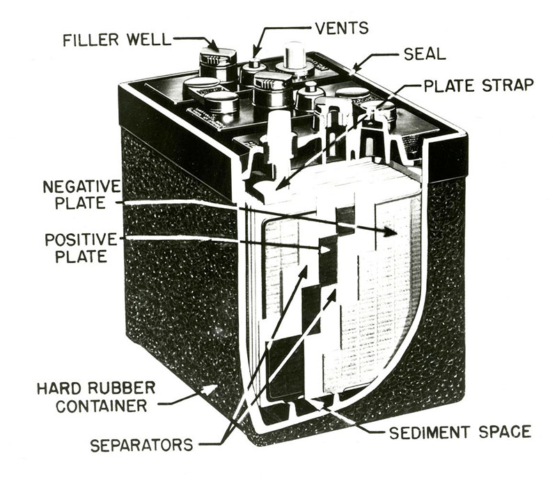
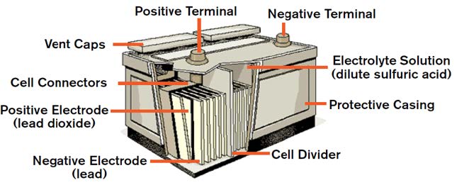
History of Lead-acid Batteries
Lead-acid is the oldest rechargeable battery technology in existence. Invented by the French physicist Gaston Planté in 1859, lead-acid was the first rechargeable battery to be used in commercial applications. More than one hundred fifty years later, we still have no real cost-effective alternatives for cars, boats, RVs, wheelchairs, scooters, golf carts, and UPS systems.
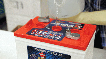
The lead-acid battery is still the most widely used 12 V energy storage device. A lead-acid battery is an electrical storage device that uses a chemical reaction to store and release energy. It uses a combination of lead plates and an electrolyte to convert electrical energy into potential chemical energy and back again.
There are many newer battery technologies available in the marketplace. However, lead-acid technologies are better understood and are widely accepted as the standard by which all other batteries are measured. Newer technologies often have operational constraints, including maximum and minimum operating temperatures and special charging requirements that make them less versatile and useful for the average consumer in everyday applications.
Amorphous Silicon Solar PV Panel
Amorphous silicon is the oldest thin-film technology and arguably the best. When laid on a substrate, amorphous silicon does not require a grid configuration to conduct electricity, allowing it to be used on large areas with ease. However, it does not conduct as well as crystalline silicon solar PV cells used in rigid panel technology because the connections between the silicon atoms are not as consistent. This inconsistency results in interrupted electron flow.
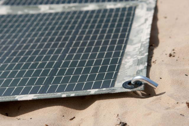
Numerous substrate materials can be used with amorphous silicon, making the technology highly adaptable. Polymer plastic is one option for substrate. Because polymer plastic is flexible and able to be folded or rolled, it excels in applications requiring ease of storage or transport.
Amorphous silicon solar PV panels perform better in low light intensities. This makes amorphous silicon a good choice for environments with interrupted sunlight or dusty conditions.
A rigid monocrystalline solar PV panel is distinctly recognizable by the arrangement of the individual solar PV cells (squares with no corners) that appears as a uniform, flat color.
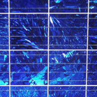
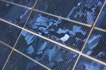
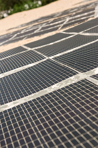
The surface of a rigid multi- or polycrystalline solar PV panel has the appearance of a rectangular grid and more of a bluish speckled color.

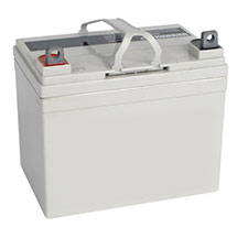
Most industrial flooded deep-cycle batteries use lead-antimony plates. Antimony is a metal that stiffens the lead plate and helps prevent battery failure due to structural failure of a plate. This improves the plate’s life but increases gassing and water loss. Antimony is not necessary in AGM batteries due to the rigid construction of the overall battery.


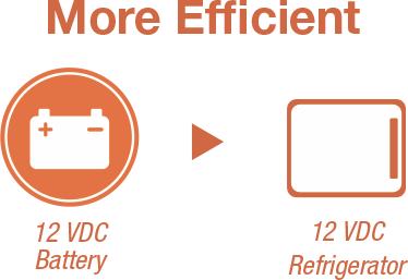
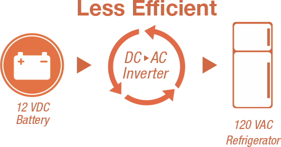

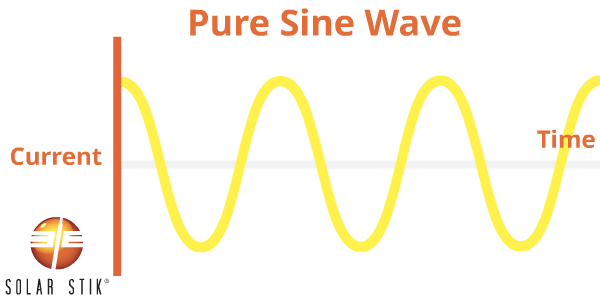
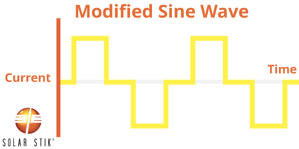
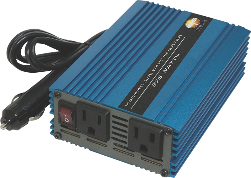
The following appliances may experience problems when operated from MSW inverters:


History of Lead-acid Batteries
Lead-acid is the oldest rechargeable battery technology in existence. Invented by the French physicist Gaston Planté in 1859, lead-acid was the first rechargeable battery to be used in commercial applications. More than one hundred fifty years later, we still have no real cost-effective alternatives for cars, boats, RVs, wheelchairs, scooters, golf carts, and UPS systems.
The lead-acid battery is still the most widely used 12 V energy storage device. A lead-acid battery is an electrical storage device that uses a chemical reaction to store and release energy. It uses a combination of lead plates and an electrolyte to convert electrical energy into potential chemical energy and back again.
There are many newer battery technologies available in the marketplace. However, lead-acid technologies are better understood and are widely accepted as the standard by which all other batteries are measured. Newer technologies often have operational constraints, including maximum and minimum operating temperatures and special charging requirements that make them less versatile and useful for the average consumer in everyday applications.
 Power Generation
 Energy Storage
 System Architecture
 Electricity Basics
 Power Management